
DDM Experts Knowledge “Asked – Known!”
How to calibrate flow meters for my specific application?
Knowledge transfer for monitoring your measuring equipment
As a sensor manufacturer, we calibrate the flow sensors produced in-house on a daily basis. We are happy to pass on this know-how. Together we discuss and finally agree on a calibration procedure to best match your specific application demands. This gives you exactly what you need to ensure a perfect traceability.
Our calibration service for flow measurement: Fast response time and always customer-focused
We can ideally serve the constantly increasing requirement for calibration services with our extensive and first-class laboratory equipment. Scheduled flow calibrations can be processed within 5 working days!

Our scope – your PLUS in service
- fast response time and maximum customer orientation
- optimally equipped calibration laboratory with visco- and density meter
- from 0.01 to 550 liters per minute
- from 0.7 to 1400 mm2/s
- Calibration fluid water or oil
- Devices under test (DUT) with frequency, voltage or current output
- As found calibration
- Adjustment
- As left calibration
Download inquiry forms
We look forward to your inquiries.
In the following Good Practice Guide, you will find basic information on the general principles of calibrating liquid flowmeters. You will learn more about the various calibration methods and receive valuable expert tips and advice from our calibration specialists.
- Calibration of flow meter – introduction
- What is Calibration?
- Flow Rate, Quantity and Time
- Repeatability and Reproducibility
- Resolution
- The Importance of Calibration Fluid and Conditions
- Flow profile
- Traceability, accuracy and uncertainty
- Accreditation
- Reporting the result – performance indicator
- Calibration frequency or how often should a flow meter be calibrated?
- Calibration Methods for Liquids
- Expectations for a Calibration
- Scope of flow meter calibration services at DDM laboratory
Calibration of flow meter – introduction
This good practice guide is intended to provide an overview of the general principles of flowmeter calibration. It has been prepared for operators of flowmeters who need to have calibrations performed. It is intended to help, together with the calibration service provider, to define the type and scope of calibration and to match the conditions to the flow meter process environment as close as possible.
The guide first covers the general principles of calibrating devices for measuring flowing liquids (flow meters).
The vocabulary used is important in understanding these principles to provide a clear picture of what is meant when various terms are used in defining a calibration.
The main definitions of terms were taken from the “International Vocabulary of Metrology – Basic and general concepts and associated terms” (VIM) 2008, which is freely available on the BIPM website. (The BIPM is the international body for harmonization of metrology). Where appropriate, the older definitions from the previous version VIM (1995) have been used where this provides a clearer definition than the latest.
What is Calibration?
Calibration embraces a number of operations, systems and concepts. This is best explained in a series of descriptions.
Calibration
Definition Calibration
operation that, under specified conditions
establishes a relation between the quantity values (with measurement uncertainties) provided by measurement standards and corresponding indications (with associated measurement uncertainties) uses this information to establish a relation for obtaining a measurement result from an indication.
VIM 2008 – (2.39)
The formal definition of ‘calibration’ taken from the VIM is given below.
What has to be done now is to examine how this applies to flow measurement.
Calibration is a comparison between the reading of a device and that of a standard. The process which establishes this relationship is a set of interrelated measurements and operations which provide the comparison. Flow measurement does not rely on a single operation and so neither does a flow-based calibration. Measurement of the quantity of fluid depends on establishing the basic quantity and a number of influence factors. The quantity of fluid may be expressed as a volume or a mass. The measurand may be the quantity or the ‘rate’ i.e. the quantity per unit time. The quantity measured by the standard may be different from the quantity passed through the test device due to changes in volume or even mass between the meter and the standard. Changes are usually related to the influence factors such as temperature, pressure, viscosity and expansion.
Influence factors of calibration
This combination of fluid, influence factors, the standard and the device come together to define a set of operations which to provide the calibration. As the fluid and influence factors all affect the meter performance, the calibration is carried out ‘under specified conditions’ and these must be defined’.
A calibration is not an absolute operation. It is a comparison between the measuring instrument, in this case the device under test or flow meter, and the standard. Through this comparison, a relationship between the quantity measured by the device under test and the measurement of the same quantity derived from the standard is established. This is expressed in some way which gives a meaningful expectation of how the device will perform in use. The comparison during a calibration is against a standard. The standard comprises the system of pumps, pipes, fluids, instrumentation, quantity reference measurement, calculations and operators. These all combined provide a measure of the quantity of fluid passing through the device or flow meter being calibrated.
The measurement of fluid flow is dynamic and all measurement devices are affected in some way by the conditions of use. It will be impossible to have a standard which fully reproduces the conditions under which the meter will be used in practice.
Flow devices are affected by:
- temperature
- viscosity
- flow profile
- flow rate fluctuations
- pulsations
They are also affected by the external environment, vibration, stress and temperature etc. Different devices are affected in different ways. Similarly the standard will also be susceptible to these same influences. Since a calibration is a comparison between the measurement made by the device under test and that realised by the standard, the resultant relationship will be for the specified conditions; therefore a further assessment of the relevance to the final application must be carried out.
DDM TIP from our calibration experts
Selecting the standard will be a compromise to best replicate the conditions of use while providing a suitable reference standard measurement. The standard must also be compatible with the performance and characteristics of the meter to be tested and the result desired
Flow Rate, Quantity and Time
Definition Response time
time interval between the instant when a stimulus is subjected to a specific abrupt change and the instant when the response reaches and remains within specified limits around its steady value.
VIM 1995 (5.17)
The mechanism by which a flow measurement device gives a reading of flow is dynamic. The sensor reacts to the flow of fluid through it or past it to realise an output related to the flowrate or the quantity passing.
DDM TIP from our calibration experts
Measurement of flowrate and quantity are related through the time interval across which the quantity is measured. In practice the end user of the device has different expectations for the behaviour and hence the calibration. In establishing this relationship it is vital to relate the response time of the device to the calibration method. Again the current and older generic definitions of response times are given. The interpretation of response time is reasonably straightforward for mechanical meters. The mechanical interface between the fluid and the indicator can be explained and defined in terms of momentum and drag affecting the meter when the flow changes.
With the advent of electronics this has become more difficult to establish. For example, a positive displacement meter in liquid responds very quickly to changes in flowrate even very abrupt changes; the flow stops, the rotor stops and the register stops. If a pulse generator is fitted, the generated pulses stop when the flow stops. A frequency counter will not reflect this until it completes its measurement cycle which may be some seconds later. During that time, a totaliser or register will correctly indicate quantity, but the flowrate indicator will not be showing the correct (instantaneous) flowrate. If however the mechanism in the meter has play or is loose, stopping the rotor may allow the output register to ‘run on’ after the rotor stops hence generating additional quantity or pulses. A different type of meter may of course not respond to an immediate change in flow. A turbine rotor will have significant momentum and, although speeding up quickly, may take time to slow down when subjected to a change in flow, particularly in gas measurement.
Meters based on non-mechanical sensing techniques e.g. electro-magnetic, Coriolis or ultrasonic meters, have different response characteristics. For example, an electromagnetic meter may take some time to establish and measure a change in the generated voltage after a change in flow, while an ultrasonic meter output is the average of a number of measurement cycles and this averaging may take appreciable time to complete. Most meters based on non mechanical sensing, and some mechanical meters, have a microprocessor which calculates the output quantity from the sensor signal. For some meter types this is an additional capability while others require this processing to convert the sensor signal and correct for influence factors before calculating and generating an output signal. The output signal can be a pulse frequency or a current (mA) output generated from this calculation process. A digital display may be added to show the required output value and many modern meters have digital outputs to transmit the chosen measurement(s) to a remote readout or computer. All these outputs will have a different response times delaying the raw sensor response by the signal processing and calculation time. An example of a processed output signal comes from a vortex meter with a signal processor designed to smooth any pulses missed by the sensor and to increase the resolution of the output. Such a device may have output response times of many seconds even though the sensor itself has responded in under a second.
DDM TIP from our calibration experts
Modern flow meter types such as Coriolis, electromagnetic, or ultrasonic meters are totally dependent on microprocessor-based output, and the variety of settings to average, damp or cut-off low flowrates must be understood and selected to ensure the response time matches the limitations of a calibration method. Matching the response time of a device to the chosen calibration method is a vital part of the process. If the device response time does not match the time within which a calibration test point is taken, poor repeatability or calibration offsets may be observed. This response time may however be perfectly adequate or even advantageous when the meter is in service.
Repeatability and Reproducibility
Definition Repeatability
measurement precision under a set of repeatability conditions of measurement
VIM 2008 (2.21)
Definition Reproducibility
measurement precision under reproducibility conditions of measurement
VIM 2008 (2.25)
To obtain confidence in a measurement it is expected that the measurement should be able to be repeated and give the same result. In practice measurements only repeat to within a certain band over a short time and a (probably) wider band over a long time period or under different circumstances. It is generally expected that a calibration should give some indication of the repeatability of an instrument; however, it is not likely that one calibration will show the reproducibility. Repeated calibration may of course be carried out perhaps over many years to show this parameter.
Resolution
Definition Resolution
smallest change in a quantity being measured that causes a perceptible change in the corresponding indication.
VIM 2003 (4.14)
Although it may seem obvious, the resolution of the device must be adequate to allow a calibration to match the uncertainty required. To achieve this, the standard must be able to measure enough fluid to match the resolution of the device. For example if a flow meter has a resolution of 1 litre, the standard must have a volume of significantly more than 1,000 litres to achieve an uncertainty of 0.1%. To meet oil industry norms, a volume of 10,000 litres would be expected to ensure an achievable uncertainty of 0.01%.
The Importance of Calibration Fluid and Conditions
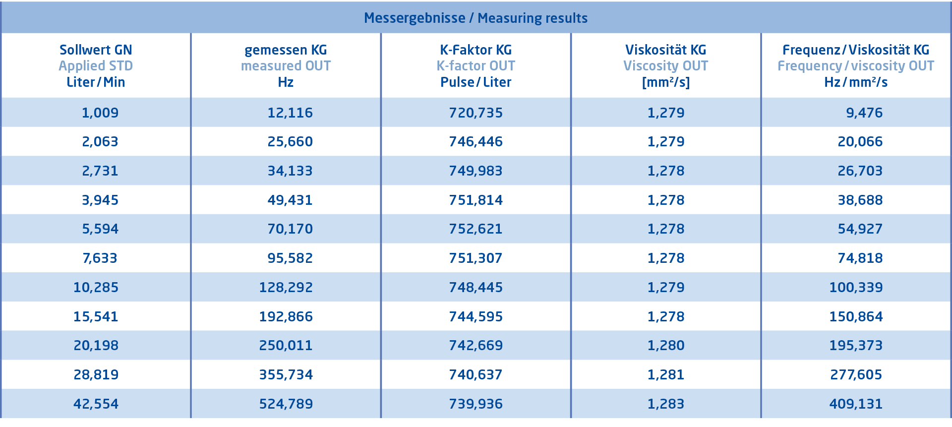
All flow meters interact in some way with the flowing fluid. The nature of this interaction is affected by the properties of the fluid or the velocity distribution of the fluid passing through the device. Changes in this interaction alter the ability of the device to give an accurate representation of the quantity. The magnitude of the error is different for different meter types and fluids. For this reason, it is desirable to calibrate using the same fluid and pipework configuration within which the meter will normally operate. This is clearly not often possible; the meter has to be installed in a test laboratory, or calibration standard has to be installed in the process application. In either case some degree of disturbance to the meter is inevitable. The best economic compromise must be established in choosing the calibration. This will be based on the final duty of the meter, the required uncertainty and knowledge of the meter performance. For other meter types, such as turbine meters, the choice of calibration fluid is particularly important.

Turbine meters are viscosity sensitive, and the figure opposite shows some typical calibration results from a turbine meter using water and three petroleum products. Because of this sensitivity to viscosity, it is important to calibrate these meters using a fluid as close to the viscosity of working fluid as is practicable. For this reason, among others, fiscal meters for oil are often calibrated on site using a dedicated pipe prover.
DDM Calibration Service: State-of-the-art for your flow measurement!
We determine the density and viscosity of customer-specific media at several temperatures distributed over the real usage range of the respective application. This provides an optimal viscosity correction of turbine flow meters.
Flow profile

When a fluid passes through a pipe, the distribution of velocity across the pipe alters to approach a ‘fully developed’ profile which is dependant on the pipe internal diameter, roughness and fluid Reynolds number. The presence of any change from a straight pipe will alter the profile drastically. Bends, double bends, valves etc. all introduce asymmetry to the velocity distribution and some introduce swirl or rotation. As the way the fluid interacts with the sensor can be highly dependent on the velocity profile, these effects must be considered in the calibration. Most calibration facilities allow adequate straight pipe lengths and the use of flow conditioners to establish predictable and reproducible flow profiles close to an ideal profile.
DDM TIP from our calibration experts
It should be noted however that care has to be taken to ensure pipes upstream of the meter have the same internal diameter as the meter inlet and step changes or misalignment of joints and gaskets do not introduce irregular profiles.
Traceability, accuracy and uncertainty
Definition Traceability
property of a measurement result whereby the result can be related to a reference through a documented unbroken chain of calibrations, each contributing to the measurement uncertainty
VIM 2008 (2.41)
Since a calibration is a comparison between the reading taken from a device under test and that of a standard, it is necessary to consider what properties are required from a standard. Firstly and most importantly, the standard should measure the same quantity as the device. There is little value in comparing a mass meter output with that of a volume tank without a measure of density to allow conversion between mass and volume. There must be confidence that the measurement taken by the standard is accurate. To achieve this all the measurements in the system have to show traceability to higher level measurements and ultimately to National and International standards. The definition of traceability provided expresses the process by which a measurement can be related through an unbroken chain of comparisons to national/international standards.
It must be noted that each step of the chain will have an uncertainty becoming smaller at each step. It must be noted that providing or claiming traceability alone makes no statement regarding the quality or uncertainty of the result; this requires an uncertainty value.
Important! Traceability must also be through comparisons to other/better calibrations and NOT TO an accreditation body.
Definition Accuracy
closeness of the agreement between the result of a measurement and a true value of the measurand
VIM 1995 (3.5)
It is contentious to use the term ‘accuracy’ in relation to calibration work. Accuracy has not the rigour or precision required to describe a scientific process. In practice however ‘accuracy’, when used correctly, is the term to which users relate and can usefully be used to express expectation and general specification. Accuracy is a qualitative term and therefore the number associated with it should be used for indicative purposes.
DDM TIP from our calibration experts
To correctly express the ‘accuracy’ of a standard or a calibration the ‘uncertainty’ must be determined and quoted. Uncertainty provides confidence that the determination of the value lies within the stated value.
Definition Uncertainty
„Parameter der die Streuung einer Messgröße, basierend auf den verwendeten Informationen, charakterisiert“
VIM 2008 (2.26)
Every standard must be assessed for the uncertainty in the determination of its measured quantity, as indeed must the result of a calibration. The uncertainty quoted for a calibration or a standard will be estimated from a detailed examination of all the components within the system, the use of the system and its history. It will specifically state for what parameter the uncertainty applies to. This parameter may be the quantity measured by the standard or the quantity passed through the device under test.
The latter is the uncertainty which is needed initially. It is stressed this is not the uncertainty of the calibration result. The resolution of the meter, the influence factors and finally the repeatability and linearity of the calibration results must all be included to provide the uncertainty of the calibration. It is also worth noting that uncertainty may vary across the flow range of the meter. The quantity of fluid collected by the standard may contribute to different uncertainties, or the meter performance may vary. In specifying the required uncertainty of a standard relative to that of a meter, it is good practice that the standard should have an uncertainty 10 times smaller than that of the requirement of device to be calibrated. Although this is a good principle, in flow measurement it is often not possible to achieve due to the high expectations of flow meters and the applications for them. A standard with an uncertainty of a factor of three lower than the requirement of the application is often all that can be achieved.
Accreditation
Accreditation is the process that a calibration laboratory or service provider undergoes to give confidence that the result provided to a client meets the expectation stated in the scope of the work.
It is a process by which the equipment, technical methods, contractual arrangements, and quality of the results are examined to give confidence to the client in the delivery of the service.
A third party, or indeed the client, accredits and organisation hence giving confidence in future works without individual inspection. This process ensures that traceability has been established, an uncertainty budget produced, and procedures are sound. To avoid multiple client accreditations, and to provide commonality, accreditation is provided by a National accreditation body and subject to meeting international agreement on the standards for inspection. Most developed countries have their own accreditation body and it is now recommended that only one body should be appointed in each country. In Germany the body is the Deutsche Akkreditierungsstelle GmbH DAkkS.
Reporting the result – performance indicator
To display the result of a calibration, the nature of the meter output has to be understood. Flow meters may indicate flowrate or quantity in a number of different ways. There may be a mechanical or electronic display indicating quantity or flowrate, or an electronic output based on pulses, frequency or current (mA) or digital.
Where the output or display is based on the ‘rate’ measurement (i.e. frequency, flowrate, differential pressure or mA), readings normally vary a little during a calibration test point. It is normal to average the readings taken at a controlled sample rate across each calibration determination. The result of a calibration is normally given in tabular form listing the measurements from the standard (GN) and the device (KG).
DDM TIP from our calibration experts
Information on the influence factors and the amount of raw data given will vary depending on the calibration specification. The presentation of meter and standard readings is not the most helpful to interpret the result of the calibration. It is therefore normal to calculate a performance indicator. A performance indicator can be used to display the result in a way which best displays the performance of the meter across the flow range. It will also allow the determination of a quantity when the meter is used in practice.
A number of different performance indicators are commonly used.
K-factor
Used for meters with pulsed outputs proportional to quantity passed. K-factor is expressed as pulses per unit quantity (e.g. pulses per m3 or pulses per liter).
Definition Correction Factor
numerical factor by which the uncorrected result of a measurement is multiplied to compensate for (systematic)
VIM1995 (3.16)
Meter factor (correction factor)
The generic definition is ‘correction factor’ in the VIM but in the flow meter industry the term ‘meter factor’ is used. The meter factor is normally dimensionless and is calculated as the ratio of the meter output to value determined by the standard. This can be computed from rate measurements or quantity measurements. Units should be the same.
z.B.

Where F is the meter factor; Q is flowrate; V is volume; i is indicated by the device and s is the measured value from the standard. As with the K-factor, this is the number which the output is multiplied to give the ‘true’ reading.
Definition Error
measured quantity value minus a reference quantity value.
VIM2008 (2.16)
Error
Definition Relative error
error divided by a true value of the measurand
VIM 1995 (3.12)
Error is the difference between the indicated value and the value determined by the standard. Relative error is the error divided by the value determined by the standard and is normally expressed as a percentage.
It is important to always define this equation in a calibration report as some industries use a different convention. This is best described as the inverse or negative error and this is based on the standard minus the indicated value.
Calibration frequency or how often should a flow meter be calibrated?
There is no correct answer to the question. In some applications an answer is apparently easy. An industry standard or third party (regulator or trading partner) dictates the calibration frequency. In this case the meter is calibrated whether it irequires it or not and is often assumed accurate between calibrations. For most applications however, it is the user who must define the calibration interval and the policy to determine when to calibrate. The calibration interval should be chosen to minimise the risk of an incorrect meter reading making a significant impact on the process. For example, high flowrates of oil attract huge tax liabilities. The product value is high, the risk of meter damage is high and so perhaps weekly in-situ calibrations of the meter, in the actual product, will be specified. Alternatively metering waste water with a Venturi may only require annual inspections, irregular verification, and no flow calibration. The differential pressure measurement device will however be calibrated regularly. The risk of the pressure transducer being in error is reasonably high, the risk of the Venturi changing is low, and the product value is low. Other factors affecting the decision are the history of the meter, when the process is closed for maintenance, or what checking and diagnostics are monitoring the meter.
DDM TIP from our calibration experts
It is always good practice to keep calibration graphs, and control charts of the meter performance. This will assist in selecting intervals and also show changes in performance indicating degradation of meter performance.
Calibration Methods for Liquids
A number of quite specific methods and systems are recognised for the calibration of flow devices for liquids. They are mainly distinguished between static and dynamic methods.
Static Methods
This method is generally preferred for meters measuring exact quantities of liquid, especially meters for batch measurement e.g. used within beverage dispensers. ‘Standing start and stop’ is the simplest method available and can be used for both high and low accuracy calibrations. calibration standards are usually classified as being ‘bucket and stopwatch’ systems. The ‘bucket’ is a container which is weighed or has a known volume. The ‘stopwatch’ is a method of measuring the time to fill the bucket.
Dynamic Methods
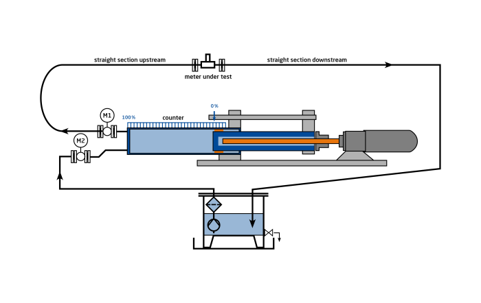
Commonly used within calibration laboratories piston provers provide dynamic calibration at reasonable accuracy levels. The so called positive displacement principle, is based on a high precision piston displacing the calibration fluid through the device under test. Piston speed is proportional to the flow rate and can be set to any desired value. During piston movement the flow rate maintained constant and can be compared with the device under test reading.
Expectations for a Calibration
The calibration and of a meter applies to that meter only, operating under the conditions with which it was calibrated. If in service these conditions are changed the calibration may not apply. What then are the real orders of uncertainty which might be reasonably obtained from calibrated meters? First, the meter cannot be calibrated to an uncertainty level better than its repeatability and the uncertainty of the standard. Systematic uncertainties can only be estimated from knowledge of the calibration system and its method of traceability and transfer through to the final duty with the addition of influence factors and historical performance being added. Liquid flow meter calibration facilities should be able to measure flowrates to uncertainty levels between 0.05 to 0.5 per cent depending upon the complexity of the system and its design.
Scope of flow meter calibration services at DDM laboratory
We are experts in the calibration of flow meters. To build up a history, we perform an
as-found calibration first. If necessary only, the flow meter under test is then adjusted. In the case of an adjustment was made, the final calibration ‘as-left’ is documenting the actual flow meter performance. Calibration certificates are provided printed and/or in digital form.
Our scope – your PLUS in service
- fast response time and maximum customer orientation
- optimally equipped calibration laboratory with visco- and density meter
- from 0.01 to 550 liters per minute
- from 0.7 to 1400 mm2/s
- Calibration fluid water or oil
- Devices under test (DUT) with frequency, voltage or current output
- As found calibration
- Adjustment
- As left calibration
We look forward to your inquiries.