To permit the flow measurement of fluids, there are a number of measuring principles. The various measuring principles, whith unique dvantages should be selected in accordance with the specific requirements and the concrete measuring task.
What is the maximum flow rate expected? How accurate and fast must the flow measurement be? Is the process media abrasive or chemically aggressive? Estimate the maximum medium temperature? What installation space is available? Let our experienced team advise you. We will find the right measuring principle and the ideal measuring device for your project. Decades of experience and our passion for our core business ensure an excellent quality standard.
Discover our intelligent and innovative products and systems for the measurement of liquid flow rate.
Can’t find the ideal solution? In that case we could offer a customized solution for your specific application. Your Mission Impossible is our passion. Get in touch with us today. Our interdisciplinary team is looking forward to your inquiries.
- Individual measurement requirement and economy in flow measurement
- Flow meters of different measuring principles at a glance
- Differential pressure devices
- Inferential devices
- Positive displacement meters
- Vortex Flow Meter
- Velocity measuring devices
- Mass Flow Meters
- Summary: Flow meter selection table by required characteristics
Individual measurement requirement and economy in flow measurement
Flow rates of liquids must be measured in countless areas of application. As diverse as the applications are, as large is the number of different flow meters offered on the market. Here, one is literally spoiled for choice.
Each flowmeter type is tailored to the specific requirements of certain measurement tasks. It is crucial to define what exactly the objective of the respective flow measurement should be.
For example, filling a quantity of juice concentrate with an accuracy of 2% is quite different from monitoring a cooling water circuit with alarming when the flow rate falls below a critical level. The correct filling of a cup of hot coffee from a vending machine places completely different demands on a flow meter than the exact determination of a fuel quantity at the pump of a gas station.
In the following, flow meters of different principles for measuring liquids are described. The focus is on the better-known types available on the market. Supplementary information is given which can serve as guides for the practical selection of an optimum flow meter for an individual measuring task. Advantages and disadvantages are summarized in each case.
In addition to the technical characteristics, the expected cost of ownership should also make a decisive contribution to the purchase decision. The determination of expected operating costs is not easy, since it is made up of a large number of individual costs.
First and foremost is always the purchase price.
However, there are also costs, e.g. for
- breakdown in the event of a device defect
- performance losses caused by measurement uncertainties
- energy costs for operating the flow meter or
- overcoming the pressure loss generated by it
- installation and cabling costs
- space requirements
- weight
- required flow staighteners
- separate display or output interfaces
The right flowmeter for the job is the one that will perform the task actually required, satisfactorily, at an acceptable fully installed cost.
Flow meters of different measuring principles at a glance
While all flowmeters can make use of the latest technology, the basic techniques are fairly well established.
Flowmeters will be described falling into six broad groups:
| Differential pressure devices | Flow meter: Pitot-Tube, Orifice Plate, Variable Area Flowmeter |
| Inferential devices | Flow meter: Flow Turbine, Pelton wheel |
| Positive displacement meters | Flow meter: Oval Gear |
| Fluidic devices | Flow meter: Vortex |
| Velocity measuring devices | Flow meter: Electromagnetic, UltraUltrasonic-Flow-Metersonic |
| Mass flow measuring meters | Flow meter: Coriolis mass flow meter; Thermal mass flow meter |
Differential pressure devices
Flow measurement using the differential pressure principle is the original method but not necessarily the best. It can be used for both simple and critical applications.
Pitot-Tube
The Pitot tube uses the differential pressure generated by fluid impacting the open end of a tube facing the direction of flow, a second tapping at ninety degrees to the first measures the “static” pressure.
It can be used, for example, to measure the speed of aircrafts and racing cars. In the pitot tube, the pressure caused by the speed of the “flowing” air is measured. The pressure prevailing in the dynamic pressure probe is a total pressure consisting of dynamic pressure and static pressure. To determine the velocity, the static pressure must be subtracted from the total pressure. The subtraction of both pressures is usually done by a differential pressure sensor.
Advantage Pitot-Tube
The Pitot tube is a simple mechanical component with small dimensions. It can thus be mounted exactly at the point where the velocity is to be measured.
Disadvantage Pitot-Tube
Because of its exposed location in the air stream, the Pitot tube is susceptible to dirt, insects, water, and icing. For aircraft capable of flying in instrument flight conditions, a heated pitot tube is mandatory because of the risk of icing.
Orifice Plate
A more frequently used method is the so-called orifice measurement. The method is based on the fact that a change in cross-section in a pipeline creates a pressure difference. Here, the square root of this pressure difference is proportional to the flow rate.
Advantage Orifice Plate
There are no moving parts in the fluid or gas. The system can be used under extreme conditions such as high pressures and temperatures. With correct selection of the orifice plate material, wear-free operation and long service life are achieved.
Disadvantage Orifice Plate
A constant, significant pressure drop results in energy loss and increased operating costs. The usable measuring range spread is limited and usually does not exceed 1:10. Up- and downstream flow straighteners are required for flow rectification. High installation costs due to complex overall design consisting of orifice plate, shut-off valves, flow straighteners, pipework and a differential pressure transmitter.
Variable Area Flowmeters
Variable Area Flowmeters also use the differential pressure principle. They are suitable for measuring volume flows of liquid and gaseous media. The meter is installed vertically in the piping system so that the medium flows from bottom to top. The medium flows through the conical body of the meter. Inside there is a float, which can move in the vertical axis. The float has a certain dead weight, which in principle causes this float to sink to the inlet port of the meter. If the medium in the piping system starts streaming, the float – as soon as the dead weight (weight force) is reached – starts to rise in the measuring cone. Due to the conical shape of the measuring device, which becomes wider towards the top, the further the float is pressed upwards, the more of the fluid can flow past the body at the same time (flow resistance).
Due to this principle, the float settles at a certain measured value when the forces are balanced. This measured value corresponds to the volumetric flow rate and can be read off the scale via the upper edge of the float.
With simple optical variable area flowmeters, flow ranges of 10:1 at accuracies down 1% are possible. Most devices can be equipped with a solenoid-driven tap that provides an analog output for signal processing. All such devices can have electronic ‘bolt-on’ analogue outputs or alarm trips, driven by a magnet in the float or flap.
Advantage Variable Area Flowmeters
Variable area flowmeters are relatively simple and inexpensive to manufacture. A variable area optical flowmeter does not require an external power supply.
Other advantages include:
- On-site display without auxiliary energy
- Independence from electrical conductivity
- measurement of smallest gas and liquid volume flows
- high repeatability
Disadvantage Variable Area Flowmeters
Variable area flowmeters must be calibrated for the corresponding fluid.For deviating fluid data, the scale must be converted according to VDE/VDI 3513. Normally they are only suitable for vertical installation with a flow from bottom to top. Variants with integrated spring resistor can also be used in other mounting positions.
Inferential devices
The best-known inferential measuring devices are flow turbines and propeller meters. In these devices, the velocity of the flowing media first generates a propeller rotation.
The rotational speed is proportional to the flow velocity and is converted into volume flow with the constant pipe cross-section area.
Flow Turbines
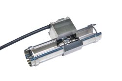
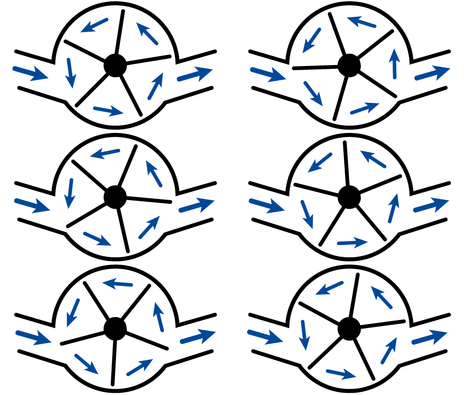
Flow turbines are the most frequently used flow meters from the group of indirect measuring devices. Their operation is simple and easy to understand. It is basically an axial flow turbine wheel (propeller) that is installed in a pipe. The medium flows around the blades of the turbine wheel and sets it in rotary motion. As the medium flow increases, the flow velocity increases and the speed of the turbine increases as well. The rotational speed is detected isolated from process media by means of an induction coil pick-off. As the speed is proportional to the flow velocity the calculation of flow rate is easy to perform.
Flow turbines are relatively small and usually have the same diameter as the process pipework. Because of this tubular design, measurements can be made easily at high pressures and temperatures. All Turbine meters are sensitive to viscosity changes and can be calibrated to achieve optimum results if fluid viscosity changes by temperature. All Flow turbines are only as good as their bearings. The smaller the turbine, the more important the running characteristics of the bearing, as the available energy of the fluid must be sufficient to overcome the bearing friction.
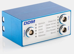
Without further correction, accuracies of up to about 0.25% at a flow range of 1:10 can be achieved. Operated by a flow computer, accuracies of up to 0.05% with a flow range of 1:100 can be realized. Pulses, analog signals or digital interfaces are available for further processing of the measured flow rate.
Advantages Flow Turbine
The miniaturized design allows the turbine meter to be fitted at applications where space is limited. The rotational speed is detected isolated from process media by means of an induction coil pick-off. Therefore, measurements can be taken even at very high process pressures. Due to the separation of turbine rotor and electronics flammable and aggressive media can be measured safe and reliable.
Disadvantages Flow Turbine
Flow turbines consist of media exposed mechanically moving parts like rotor and bearings. At Applications with frequently changing media, a residue-free cleaning or sterilization can only be realized with great effort.
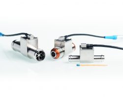
DDM Flow Turbines – innovative and miniaturized
Flow turbines VCT series cover flow ranges from 0.05 to 350 liters per minute. Housing and rotor are made of stainless steel and can be used up to 125°C and 25 bars. The process connections are manufactured threaded or with hose connections.
D The VCT rotor geometry is further optimized and supported by a high-performance hybrid ball bearing. Those improvements resulting in a wide turndown and excellent repeatability. The turbine speed is detected with no drag to the rotor and converted into a common TTL frequency output. A miniaturized media exposed probe take accurate dynamic readings of process media temperature. VCT defaults and calibration data are stored within an integrated data memory. Combined with the smart flow computer VCA or VCA-T series a plug and play flow measuring systems is operating at high accuracy and independent from fluid viscosity.
Pelton wheel
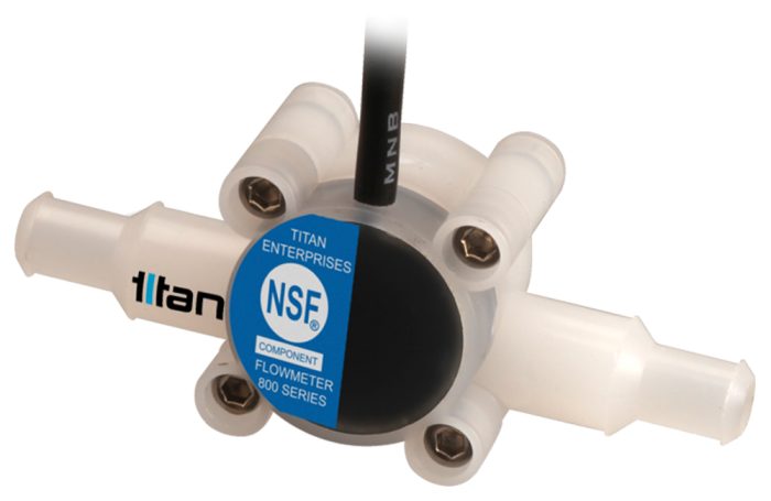
Pelton wheel meters are also known as radial flow turbines. They are particularly suitable for measuring small flow rates of low-viscosity liquids. Like a Pelton turbine, an propeller is driven by a directed jet process fluid.ring medium. The radial rotor (pelton wheel) is equipped with robust, smooth-running sapphire bearings and driven by a directed jet of process fluid. Due to the radial drive, a large portion of flow energy will be converted into the rotor speed. Therefore very robust bearings are fitted as any drag is negligible for the meter performance. Installation is simple and space-saving, as flow straightener are not required. A pulse output is realized by magnetic or optical pickoff, scanning the propeller speed. The electronic assembly is already integrated in the meter housing and hermetically encapsulated. The pulses can be measured and converted into volume flow using the individual meter K-factor [pulses/liter]. Remote display devices such as the Pulsite Solo are available as a ready-to-use solution.
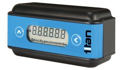
Typically, axial or Pelton wheel devices are produced in moulded modern engineering plastics, which are corrosion resistant and can be fitted with push-on fluid connectors, hose barbs or screw threads. Custom engineering of these connections allows them to incorporate panel or bulkhead mounting arrangements to suit the application, and the electrical wiring loom and terminations can be similarly customised. Due to low manufacturing costs, pelton wheel meters are particularly suitable for OEM applications such as beverage dispensing. Devices with built-in battery-powered LCD counters are used in vending machines for monitoring the dispensed volume units.
Advantage Pelton wheel
In addition to low manufacturing costs, the advantages of impeller meters include their ability to measure very small flow rates down to 10 ml/minute.
Disadvantage Pelton wheel
Disadvantages of this type of meter are the relatively large housing in relation to the line size and a larger pressure drop in relation to the measuring turbine, and lower accuracy.
DDM Pelton wheel flowmeters – small and cost-optimized
The 800, 900 and 1000 series Pelton wheel flowmeters are available in various ranges from 0.05 to 30 l/min and two temperature ranges +125°C or +60°C. The radial rotor is equipped with robust, smooth-running sapphire bearings.
The 800 series is NSF certified for food and beverage applications. The excellent chemical resistance, even for ultra-pure water, is due to the non-metallic wetted components.
For use at higher process pressures, metal housings are available for the 900 and 1000 series. They are equipped with a stainless steel housing that can be used up to a line pressure of 40bar.
Positive displacement meters
There are many types of positive displacement meters:
- Gear
- Oval gear
- Sliding vane
- Oscillatiing piston
- Helical Screw
- and many more
All have the same basic mode of operation in that they take a discrete volume of liquid and pass it from the inlet to the outlet without loss or slippage.
The measuring chamber volumes can be determined precisely and are remain constant. High-quality devices achieve an accuracy of 0.1% over a wide flow range. Due to their design, positive displacement meters work more accurately at higher viscosities, as more viscous media further minimize the gap losses of the measuring chambers and extend the usable minimum flow range.
Oval Gear
lobally the most common form of this device are likely to be domestic water meters and the meters found in petrol dispensing equipment. Because of the way these meters operate they often have a highpressure drop, particularly with more viscous fluids, but some types including the oval gear design operate with a very low differential pressure, only millimetres of head in some cases. They are very suitable for measuring oils, although some models are manufactured specifically for corrosive media: for example there is a version of an oval gear meter made from totally non-metallic plastic and ceramic components. In all cases the fluid should not contain any solid particles or stringy materials, as these would possibly jam the meshing gear or other mechanisms. The bodies for larger pipe sizes are very large, and housings suitable for high-pressure use become heavy. In the smaller sizes they are a very economic and accurate metering solution. The output of these devices is a simple pulse, which defines the passage of a defined volume of liquid. They are therefore easy to interface with simple counting electronics. Several versions have integral electronic displays and transmitters, some being battery powered.

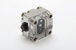
Oval gear meters are available with a transparent flanged cover which allows visual observation of the rotating gears as a simple immediate flow indication. To match the fluid properties, the housing parts can be made of stainless steel, aluminum or PEEK. A Hall sensor is incorporated to measure the oval gear speed. It uses the so-called Hall effect to sense the ceramic magnets embedded in the oval gears.
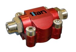
For applications in portable medical devices or robotic arms, where small size and low weight are required, miniaturized aluminium housings have been developed. The application on the robot arms monitors the flow of hydraulic oil to the press tools.
Advantage Oval Gear
- simple, reliable construction
- on-site maintenance possible (low maintenance effort)
- pulse output
- accuracy up to 0.5 %
- ATEX approval
- plain bearings ensure perfect running and long service life
Disadvantage Oval Gear
- high pressure drop
- pipe must be filled with medium and thus free of air
- necessity to install a filter in case of contamination of the medium
- no cleaning with compressed air possible
- meter blocks in case of defect (no flow possible)
- overload lead to faulty measurements and leads to wear
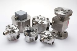
DDM Oval Gear Meter – Long service and small space requirement
OG series oval gear meters belong to the group of displacement meters. Flow ranges may vary between 0.01 to 500 liters. OG gear meters are dedicated to measure fluids such as water, coolant, engine and transmission oil or fuel. As liquid flows through the meter, a pair of oval shaped gears are forced to rotate by the flow of the liquid. These gears mesh together & force a finite amount of fluid through the meter. A Hall sensor detects the rotation of the gears to determine the displaced volume of liquid. The faster the flow rate, the faster the gears turn. The resulting pressure loss is very low due to the special tooth geometry. An excellent start-up behaviour allows measurements up to near standstill. Due to their design, oval gear meters measure independently of changes in viscosity or temperature of the process media. The installation is simple and space-saving, as no flow straighteners are required.
Vortex Flow Meter
The principle of vortex flowmeters is based on Kármán’s vortex street, whereby counter-rotating vortices occur behind a body passed by the fluid. The effect was already discovered in 1513 by Leonardo da Vinci and used to describe river flows. These so-called vortex streets were then calculated for the first time in 1912 by Theodore von Kármán and is the basis for today’s measurement technology.
Vortex Flow Meter
The following applies to so-called vortex flowmeters: if a flowing medium meets an obstacle, pressure fluctuations are built in the medium which lead to vortex shedding at this obstacle.
A particularly vivid example is fluttering flags on a flagpole.
Vortex flow meters make use of this phenomenon.

Via geometrically defined obstacles, so-called vortex or swirl bodies, vortex shedding is generated in the flow meter and its frequency is recorded with a sensor. From this, the flow rate in liquids, gases and steam can be determined. Reliable detection of vortices is rather difficult and depends in particular on the presence of extraneous noise in the pipeline. Vortex flowmeters available on the market differ greatly in terms of the sensor that picks up the frequency of vortex breaks. Essentially, a distinction must be made here between the use of pressure sensors that record the frequency directly on the basis of the pressure fluctuations (implemented, for example, with capacitive sensors, membranes or piezo elements), strain gauges that are set into oscillation by the vortices that corresponds to the vortex frequency, or thermistors that are periodically cooled to different degrees by the vortices (the evaluation is then usually carried out in a bridge circuit).
Advantages Vortex Flow Meter
- lower installation costs
- low pressure drop
- large flow range up to 45:1
- fast respond up to 0.5 seconds
- accuracy 0.75 % of reading for liquids and 1.00 % of reading for gases
- Medium properties such as density and viscosity have no influence on the measurement accuracy for Reynolds numbers >20000.
- Can be operated at wide temperature range from -200 °C to +400 °C
Disadvantages Vortex Flow Meter
- a relatively high susceptibility to contamination
- sensitivity to vibrations in the system
- minimum flow velocity required for the formation of measurable vortices is always significantly greater than zero
- Measurement is limited to one flow direction
Velocity measuring devices
In an ideal world the flowmeter would be a section of pipe with no intrusions and so no pressure drop. Two types of commercially available meter have come very close to this: electromagnetic and ultrasonic flowmeters both use full pipe bores, measure the liquid velocity and are inherently bi-directional.
Electromagnetic Flow Meter
Electromagnetic flowmeters are generally referred to as magnetic-inductive flowmeters, or magmeters. The measuring principle goes back to Michael Faraday’s law of induction from 1832. If a conductor moves in a magnetic field, a voltage is induced in the conductor.
Translated to a magmeters, this means: If a conductive medium moves through a magnetic field, a voltage is induced in the medium.
The conductive liquid to be measured flows through a tube made of non-magnetic material, which has an electrically insulating lining on the inside. A magnetic field oriented perpendicular to the direction of flow is applied from the outside by means of coils. The charge carriers, ions or charged particles, present in the conductive liquid are deflected by the magnetic field: the positive charge carriers to the left, for example, and the negative charge carriers to the right. A voltage is generated at the measuring electrodes arranged perpendicular to the magnetic field as a result of the charge separation, and this voltage is recorded by a measuring device. The level of the measured voltage is proportional to the flow velocity of the charge carriers, i.e. to their flow velocity. Due to the arrangement of the coils, a magnetic field is generated which is uniformly distributed over the entire cross-section of the tube. Asymmetries of the flow profile, caused by missing flow straighteners, do not adversely affect the accuracy of the magmeter.
Magmeters can have a flow range up to 1:100, are available for a wide range of pipe diameters, and have a low pressure drop. They can be used without problems for critical media such as wastewater, sludge or pulp and, with careful selection of the electrode material, also for aggressive liquids. For the measuring principle to work, the fluids to be measured must have a minimum conductivity.
Advantages Electromagnetic Flow Meter
- Independence from pressure, density, temperature and viscosity.
- possibility to measure solids-loaden liquids such as slurries, pulp slurries or aggressive and corrosive products
- no moving parts therefore, no wear
- very low pressure drop
- no interfering internals, measuring path corresponds to the pipeline
- very easy to clean, CIP/SIP
- high accuracy even under solid load and with gas inclusions
- high repeatability and long-term stability
- minimal maintenance and service requirements
Disadvantages Electromagnetic Flow Meter
- Minimum conductivity of typically 5 µS required
- maximum medium temperature approx. 200 °C
- minimum flow velocity approx. 0.5 m/s
- tends to inaccuracies in the raw water range, as iron deposits can reduce the nominal cross-section
Ultrasonic Flow Meter
Ultrasonic flow meters measure the velocity of a flowing medium (gas, liquid) using acoustic waves. This flow measuring device consists of two parts, the actual measuring sensor (ultrasonic sensor) and an data processing device (transmitter or transducer). The most commonly used method uses the principle of transit time difference measurement. For this method, the medium must be as homogeneous as possible and contain only a small amount of solid matter.
In simplified terms, consider two boats crossing a river diagonally on the same line, one in the direction of flow and the other in the opposite direction. The boat moving in the direction of flow takes a much shorter time to reach the opposite bank. Ultrasonic waves behave in the same way. A sound wave propagates faster in the direction of flow of the measured medium than the sound wave in the opposite direction.
The travel times are measured continuously. The transit time difference of the two ultrasonic waves is thus directly proportional to the average flow velocity. The flow volume per unit time is the result of the mean flow velocity multiplied by the respective pipe cross-section of the transducer.
For small and medium pipe diameters, one ultrasonic path is sufficient to scan the flow cross-section with sufficient accuracy. Depending on the arrangement of the sensors, different path lengths can be realized for different pipe diameters. For very thin pipes, the path and thus the signal propagation time from one sensor to the other would be too short to be able to determine a sufficiently accurate transit time difference. In such cases, the ultrasonic path is extended by reflection from the inner wall of the tube.
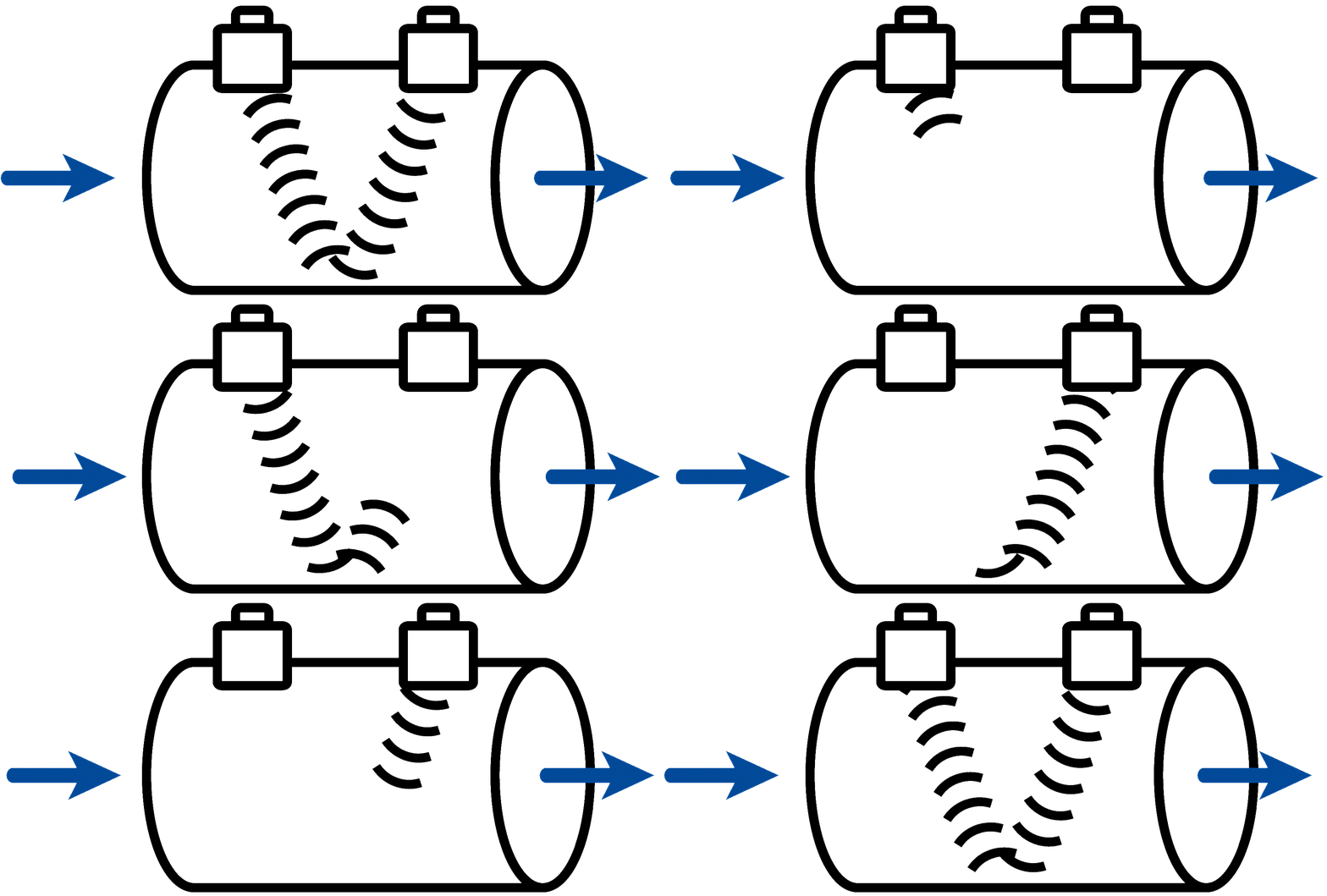
For very large nominal diameters or for asymmetrical flow profiles caused by pipe bends or fittings on the inlet side, several differently arranged ultrasonic sections are installed to increase the accuracy of the flow measurement by averaging the flow profile over the cross-sectional area.
The first ultrasonic flow meters developed around 1978 worked according to the so-called Doppler method. The application of this measuring principle requires an inhomogeneous medium loaded with solids or air bubbles. In the simplest version, a single ultrasonic transducer is used, which acts both as a transmitter and receiver of acoustic waves. An ultrasonic signal is sent into the flowing medium. A portion of the acoustic energy is scattered by the inhomogeneities (particles or air bubbles) and reflected back to the receiver. After a specified time, the pulse emission is repeated. On the basis of the transit time differences of the scattering echoes between successive pulse emissions, the movement of the scattering particles and, accordingly, the flow velocity in the axial direction can be inferred.
Advantages Ultrasonic Flow Meter
Acoustic flow measurement offers several advantages over other measurement methods. The measurement is largely independent of the properties of the media used, such as electrical conductivity, density, temperature and viscosity. The absence of moving mechanical parts reduces maintenance and there is no pressure loss due to cross-sectional constriction. A large measuring range is among the other positive features of this method.
Disadvantages Ultrasonic Flow Meter
Flow straighteners for a symmetrical flow profile as well as devices with several integrated ultrasonic sections are required. In addition, a relatively low accuracy of only approx. 1% results.
DDM Ultrasonic-Flowmeters – accurate and fully flexible
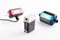
Ultrasonic flowmeters are precise flowmeters for liquids. The Atrato series of instruments can measure flow rates from 0.002 to 20 liters per minute. The flow tube has a smooth surface and contains no internals. The tube material can be chosen between stainless steel, peek and glass. For special requirements, there is the Metraflow series available. It is ideal for any application requiring a truly non-contact measurement system with a single uninterrupted, FDA approved PFA tube as the only contact material with the fluid being measured. DDM ultrasonic flowmeters generally have no internals in the flow tube. This allows measurements of high purity media as well as contaminated liquids. The velocity of the flowing medium is determined by measuring ultrasonic transit times. Using the inner diameter of the flow tube, the flow rate is calculated from this. This method is independent of pressure, temperature, conductivity and viscosity of the fluid. Ultrasonic flowmeters are characterized by low pressure drop, minimal maintenance and long service life. The measured flow rate is available via analog outputs or an integrated LCD display.
Mass Flow Meters
A mass flow meter, also known as an inertial flow meter, is a device that measures the mass flow rate of a liquid moving through a pipe. The mass flow rate is the mass of the fluid flowing past a fixed point per unit time.
The mass flow meter does not measure the volume per unit time (e.g., cubic meters per second) flowing through the device, but the mass per unit time (e.g., kilograms per second). The volume flow rate is the mass flow rate divided by the density of the fluid. If the density is constant, the relationship is simple. If the density of the fluid varies with temperature and pressure, for example, a correction must be made.
Coriolis Mass Flow Meters
A Coriolis mass flow meter is a flow measuring device that measures the mass flow of liquids or gases flowing through it. The measuring method is based on the Coriolis principle. It utilizes the fact that a flowing mass, liquid or gas, when accelerated in a curve, produces a reaction force at ninety degrees to the direction of acceleration.
The resulting force or movement is directly proportional to the mass flow rate. Coriolis systems directly measure the mass flow rate and simultaneously density and medium temperature. This allows direct conversion to volumetric flow. Coriolis Mass Flow Meters measure very accurate. For homogeneous media, accuracies of 0.15% and better can be achieved.
Advantage Coriolis Mass Flow Meters
- universal measuring system for mass, density and temperature, independent of conductivity, flow straighteners, flow profile, medium density and thus of pressure and temperature
- direct mass flow measurement without conversion
- very high accuracy (typically ± 0.15 %, special sensors up to ± 0.05 %)
- multivariable measuring principle, simultaneous measurement of mass flow, density and temperature
- no moving parts (the measuring tubes move a maximum of 30 µm, therefore one speaks of no movement – thus wear-free).
Disadvantage Coriolis Mass Flow Meters
- Relatively high price level
- Restrictions in the application with multiphase media or high gas content
- Deposits can result in errors, especially during density measurement
- limited choice of materials for wetted parts, corrosion must be given special attention
- Necessity of homogeneity of the medium to be measured
- Pressure drop
Thermal mass flow meters
Thermal mass flow meters are capable of direct measurement of mass flow. This is in contrast to most other methods, which measure volumetric flow and require separate temperature and pressure measurements to calculate density and ultimately mass flow.
Thermal mass flow meters can be divided into three different sensor principles:
- Bypass principle for gases
- Inline/CTA principle for gases
- Inline/CTA principle for liquids
Bypass principle for gases
As shown in Figure A, part of the gas flows through the sensor, which is heated by the heater RH. This results in an increasing temperature difference between T1 and T2 as the mass flow rate increases, as shown in Figure B. The temperature difference is directly proportional to the mass flow rate. Electrically, the temperatures T1 and T2 are recorded by the two measuring resistors RT1 and RT2.
If no flow is measured, the temperature difference between the two points is zero. If the flow increases, the temperature at the first measuring point (T1) decreases because the fluid dissipates heat (as shown in Figure B). At the same time, the temperature at the second measurement point (T2) increases because the fluid carries heat with it. A larger flow rate results in a larger temperature difference, and this temperature difference is directly proportional to the mass flow rate. From an electrical point of view, the temperatures T1 and T2 are the temperature-dependent resistances RHT1 and RHT2.
Inline/CTA principle for gases
CTA is the abbreviation of “Constant Temperature Anemometry”, which is also called direct flow measurement or inline measurement. In this operating principle, no bypass sensor is used; the entire flow is in direct contact with the flow sensor. Within the various flow measurement methods, thermal mass flow measurement based on the CTA principle is used for both gases and liquids. Mass flow meters based on the CTA principle cover a wide variety of measurement and control applications in almost all industries.
Mass flow meters with an inline sensor (no by-pass) consist of a straight flow channel in which two stainless steel probes are embedded. One of these probes acts as a heater, while the other senses temperature. A constant temperature difference (ΔT) is created between the two sensors. The energy that must be applied to maintain this delta-T is proportional to the mass flow. Based on this concept, it is possible to measure the flow rate with almost no pressure loss. The unavoidable small pressure drop that nevertheless occurs is caused by the gas ports and mesh screen that are recessed into the instrument body for flow conditioning. Compared to conventional thermal mass flow meters and mass flow controllers with by-pass principle, the design of the direct flow meters with CTA principle (constant temperature anemometry) is far less susceptible to moisture and contamination in the measured medium.
Inline/CTA principle for liquids
Thermal mass flow sensors for liquids based on the CTA principle do not have the probes with which sensors suitable for gases are equipped. In mass flow meters for liquids, the sensor is built around a stainless steel tube, with no moving parts or obstructions. The heating and sensor unit is arranged around the tube. According to the CTA principle, a constant temperature difference (ΔT) is generated. In this case, the first element acts as a temperature sensor and the second element acts as a heater, as shown in Figure A. The heater is heated to a certain constant temperature difference (ΔT) above the medium temperature. The actual mass flow rate is calculated by measuring the variable energy required to maintain the constant temperature difference as the fluid flows across the sensor.
Advantages mass flow meter
- no moving parts in the flow, as for example with turbines or floats, so that this sensor can also be used with solid-body loaded flows
- the medium to be monitored touches only one material
- compact design
- one sensor (probe) for different nominal sizes
- low pressure drop
- high operating pressures, up to 200 bar
Disadvantages mass flow meter
- Can only be used in the lower temperature range max. 70 °C
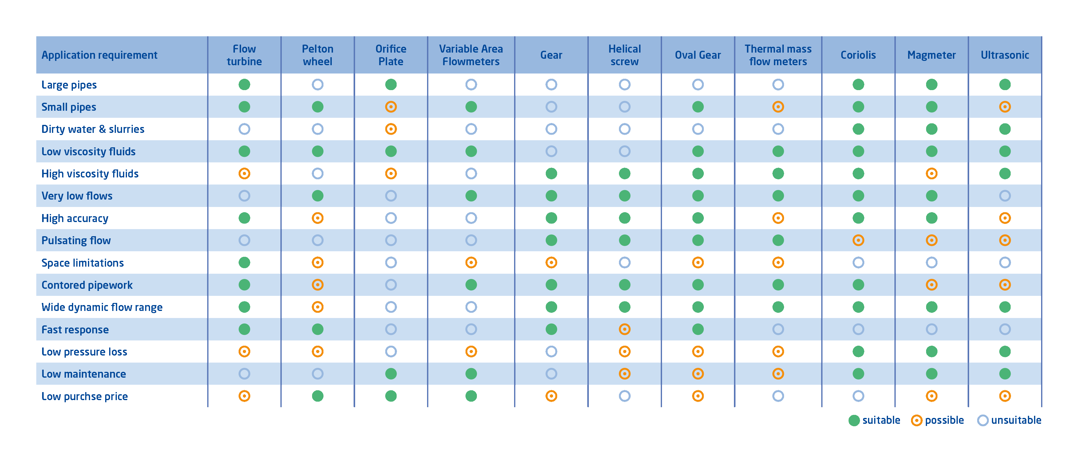
Summary: Flow meter selection table by required characteristics
The table below shows a brief summary of the flowmeters described and their suitability for different applications
TIP: Flow meter mounting influences
After the successful selection and purchase of a flowmeter, it is easy to reduce its performance and measurement accuracy due to improper installation. Depending on the measuring principle selected, incorrectly dimensioned inlet and outlet sections can, under certain circumstances, significantly reduce the accuracy of flow meters. Pipe bends, valves, tees, pumps, and obstructions of any kind can cause an unbalanced flow profile. All instrument manufacturers specify the accuracy of their flowmeters in compliance with the specified installation conditions. Any deviation from this can reduce the measurement accuracy. Even if the piping is perfect, the measurement can be affected by electromagnetic interference coupled in through the measurement signal lines. Signal lines should be shielded and routed separately from high-energy lines.


