


DDM Experts Knowledge “Asked – Known!”
How do turbine measuring systems work and what are the user benefits in flow measurement?
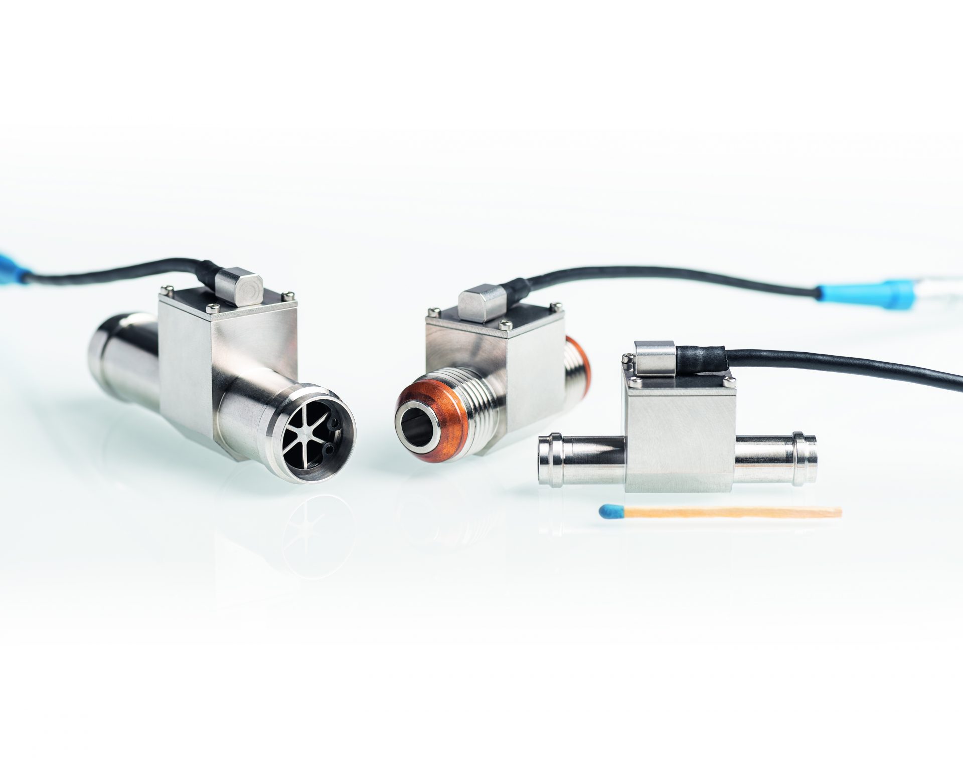
Turbine measuring systems – fast, accurate and with low space requirements
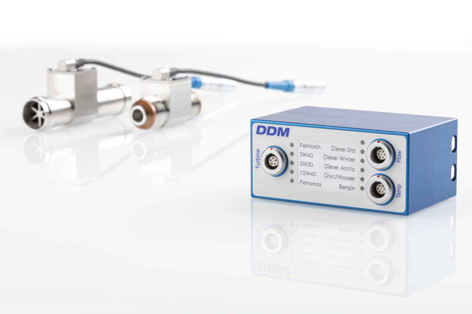
DDM Turbine flow measurement systems impress with their very fast and accurate measurement. A measuring system consists of a flow sensor, the so-called measuring turbine, and a flow computer that processes the measured data in real time.
Due to the miniaturized housing, DDM turbines (VCT) can be accommodated in a very small space. Fluid flows axially through the turbine’s measuring tube, causing the turbine wheel to rotate. An integrated signal tap detects the speed of the turbine wheel and generates a digital frequency signal proportional to the instantaneous flow. The measurement data acquisition and A/D conversion is integrated in the turbine housing.
All wetted parts of the turbine flow meters are made of stainless steel or ceramic. Thus, even flammable and aggressive substances can be measured safely.
The DDM Flow Computer (VCA) processes the raw turbine flow data and generates standardized output signals for further processing.
Application par excellence – one vehicle tests and thermal management trials
Turbine measurement systems from DDM are tailor-made for use in flow measurement in road tests as well as in the testing and inspection of complex thermal management in vehicles with electric motors. The DDM turbine flow meter with wetted thermocouple (VCT) has been further developed specifically for this purpose. You can find out more about the main areas of focus here.
Your “Mission Impossible” is our passion. We are happy to manufacture customer-specific designs on request.
Our team is looking forward to your task.
Learn in the following practical guide many more details about the mode of operation as well as the user benefits of turbine measuring systems in flow measurement.
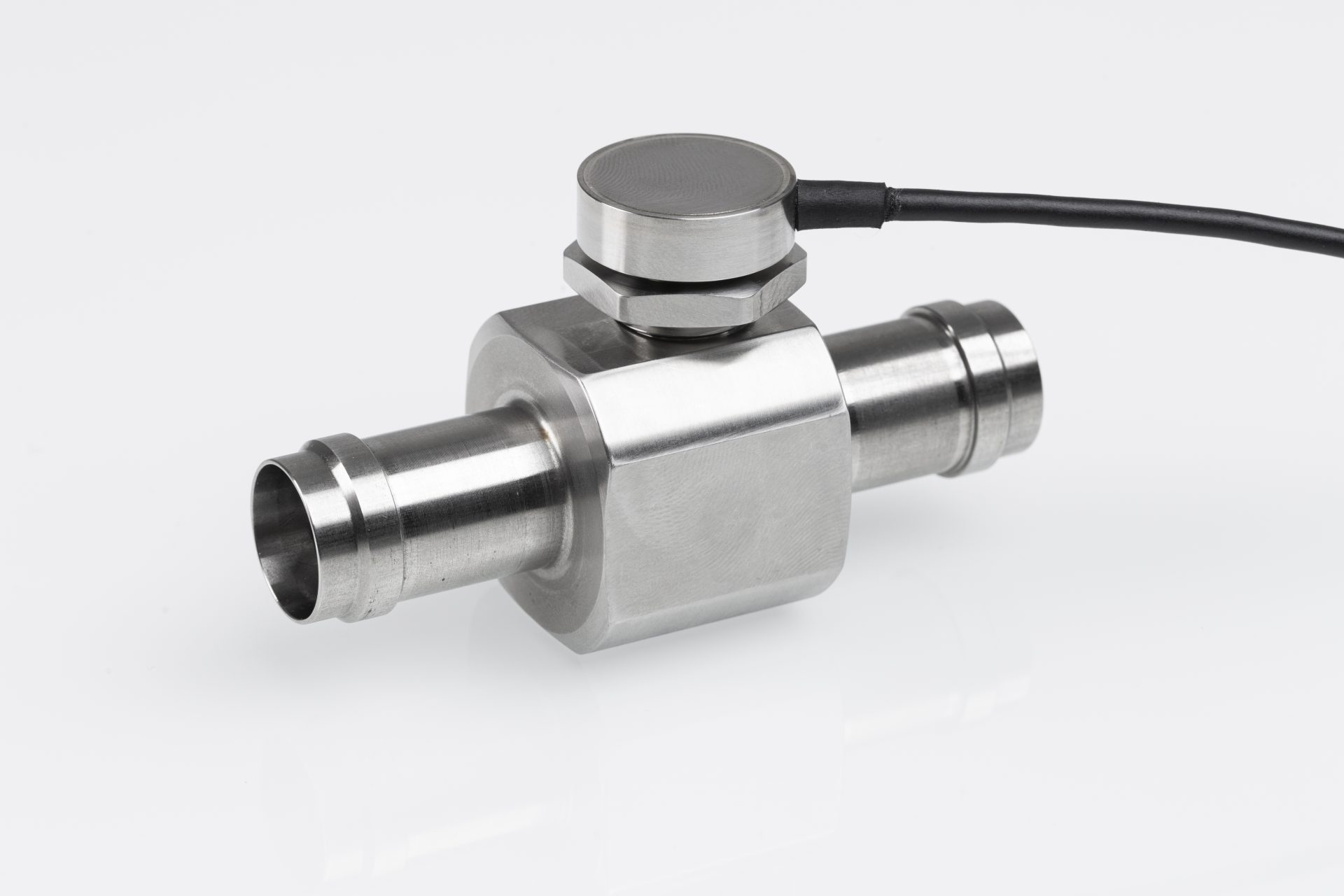
Structure Turbine flow meter
The flow passes axially through the measuring tube of the turbine. Due to the optimized flow straightener turbulences in the incoming medium are minimized.
User benefits:
No additional inlet section is required to achieve a homogeneous flow profile. As a result, the overall installation length is very small and the space requirement is minimal.
The measuring medium is directed onto the turbine wheel blades via so-called flow cones. The turbine wheel is mounted on a high performance hybrid ball bearing with stainless steel cage and ceramic balls.
User benefits:
This combination of materials ensures a certain emergency running property in non-lubricated or low-lubricated operation.
The turbine wheel has flow-optimized shaped vanes, which make it possible to realize a measuring range spread of 1:100 (example measuring range from 1 to 100l/min).
User benefits:
In addition to the large measuring range spread, the pressure loss in particular is reduced. The installation of a measuring turbine has only a minor effect on the hydraulic properties of the system to be measured.
In the direction of flow, directly behind the turbine wheel you will find a type T thermocouple which directly measures the temperature of the medium.
User benefits:
A dynamic, calibrated temperature measuring point is available without additional costs or space requirements.
Integrated measuring electronics
The measuring electronics integrated in the turbine housing digitizes all raw data. This ensures trouble-free operation even when used in electric vehicles or other EMC-critical applications.
Signal pickup and processing
The speed of the turbine wheel is proportional to the flow rate. An oscillating circuit is used to detect the rotational speed, which is installed in the housing of the turbine. The coil of the oscillating circuit is excited by a carrier frequency and generates a magnetic field. As the impeller rotates, the blade tips pass through this field and amplitude modulation (RF) of the carrier frequency occurs. The amplitude change is decoupled and is proportional to the flow rate. After decoupling, the amplitude change per time is converted to a TTL level frequency signal. This useful signal is proportional to the rotational speed of the turbine wheel and thus the flow rate. This type of sampling produces no braking effect (zero drag) on the blades of the turbine wheel.
User benefits:
Due to the feedback-free signal pickup, large measuring range spreads can be realized. In contrast to flow meters with magnetic or Hall signal pickup, a DDM measuring turbine can be used with a spread of 1:100. The raw signal of the turbine frequency is converted directly in the housing of the measuring turbine into a TTL / open collector signal. This signal level allows reliable digital transmission of the turbine frequency over long distances and increases immunity to interference in the demanding environment of electrically driven vehicles.
Thermocouple
A type T thermocouple is immersed in the measuring tube of the turbine flow meter. Due to the direct media contact, a dynamic temperature measurement is achieved. Unlike temperature measurement in the pickoff of a turbine, the influence of the ambient temperature is significantly minimized in the case of temperature measurement in contact with the medium.
DDM Practical Check!
DDM has carried out a comparative measurement on a temperature-controlled flow calibrator. The aim was to find out the dynamics of a wetted thermocouple compared to a temperature measurement in a pickoff. In addition, the influence of the ambient temperature was to be determined.
For this measurement, the DDM turbine flowmeter with wetted thermocouple (VCT) and a turbine with commercial RF pickoff with temperature measurement in the pickoff were used. These two turbines were installed in a shut-off bypass of the temperature-controlled measuring section. The measuring section of the calibrator can also be shut off, so that opening the bypass closes the measuring section and the complete temperature-controlled liquid flows through the bypass.
The bypass is first filled with calibration liquid and then shut off. The calibrator constantly conveys liquid through the measuring section to heat it up. A temperature difference of 60°C is established between the 90° hot measuring section and the 30°C hot bypass.
By abruptly opening the bypass and closing the measuring section, the hot liquid is passed through the two turbines. The reference temperature of the test rig drops as the 30°C fluid from the bypass mixes with the 90°C fluid.
You can immediately see that the temperature measurement of the wetted thermocouple rises rapidly and converges to the reference temperature of the calibrator. The temperature measurement in the pickoff, on the other hand, is very sluggish and the influence of the ambient temperature of about 30°C can be clearly seen. There remains an offset from the actual media temperature in the temperature measurement of the pickoff.
User benefits:
The medium temperature measured by the integrated thermocouple is sufficiently dynamic and accurate. The temperature measuring point is calibrated and can be used, in addition to the flow rate, as a full-fledged measuring point.
In the head of the DDM turbine flow meter, the measured temperature of the thermocouple is converted and output digitally. This leads to a transmission-safe communication to the flow computer (VCA).
Data memory in the turbine flow meter
The calibration data of each turbine flow meter is stored in a data memory in the turbine housing. This allows a DDM turbine (VCT) to be freely combined with any DDM flow computer (VCA). DDM measuring turbines (VCT) are generally so tightly calibrated that they can measure all liquids in the viscosity range from 1 to 75 mm2/s without additional calibration effort.
User benefits:
Fast availability, delivery from stock, universally applicable for a large number of liquids.
Flow-Computer
The DDM flow computers VCA (viscosity compensated amplifier) linearize and viscosity correct the measured flow and output it as an analog or digital signal. In order to be able to use the flow computers universally with different liquids, up to 10 customer-specific media characteristics can be stored and selected without tools by means of an RFID tag.
User benefits:
Measuring media can be changed directly without any programming effort.
Automatic parameterization
The flow computer (VCA) reads the data from the memory of the turbine flow meter (VCT) and parameterizes itself. In addition to the calibration data / UVC characteristic curve (Universal Viscosity Curve), the turbine data contains the main characteristics of the turbine flow meter, such as serial number, measuring range, calibrated measuring range and compensated viscosity, also the setting parameters for the output signal of the flow computer.
The turbine specifies to the flow computer for which measuring range which output signal should be given, e.g. flow from 0 to 40l/min corresponds to an output signal from 0 to 10V.
User benefits:
The output signal scales automatically based on the connected turbine.
Signal processing
The flow computer measures the frequency signal (TTL / open collector) of the turbine flow meter and reads the temperature signal of the thermocouple. The media temperature is used to compensate for the viscosity influence of the media via the stored media characteristic curve (viscosity versus temperature).
The real-time viscosity corrected and linearized flow rate is D/A converted and output as a voltage value. From measuring the turbine frequency to setting the output voltage, the DDM flow computer requires 200µsec.
User benefits:
Fast changes of flow rate and temperature can be recorded accurately and almost without delay.
Update rate
The update rate determines the time interval from the acquisition of the turbine frequency to the change of the output signal of the flow computer, over this time interval an averaging of the turbine frequency takes place. With an update rate of 0.5 sec, the average value of the flow over 0.5 sec is output in proportion to the span.
The DDM flow computer offers the possibility to display a “live” mode, in this mode the frequency of the turbine flow meter is measured linearized viscosity corrected and immediately output as a voltage signal. In this live mode the output signal is reset min. every 200µsec.
User benefits:
An individual adaptation of the averaging to the requirements of the application can be realized.
Cut-off
The cut-off describes the period after which the output signal is set to minimum (0V) if no turbine frequency is detected.