


Pressures in liquids and gases need to be measured in countless application areas. As varied as these applications are, so too is the array of pressure sensors available on the market. Here, one literally faces an embarrassment of choices.
This page will describe pressure sensors of different measuring principles for liquids and gases. The focus is on the more well-known types currently available in the market. Additionally, information is provided that can serve as practical guidelines for selecting an optimal pressure sensor for a specific measuring task. The advantages and disadvantages of each are concisely summarized.

DDM – Long-Term Stable and Precise Pressure Sensors for Demanding Tasks in Pressure Measurement
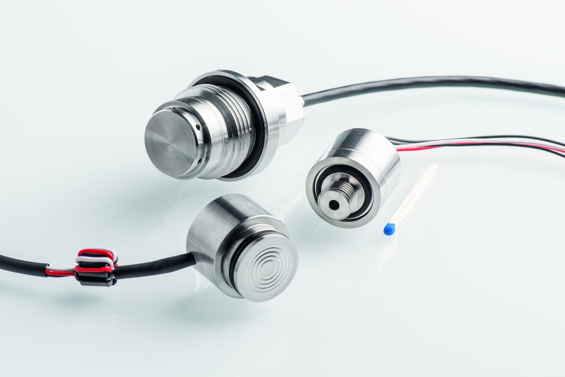
Our pressure sensors are developed and manufactured by our experienced and competent team at our Fulda site. Each of our quality products is optimized and delivered for customer-specific requirements and concrete measuring tasks. In-house manufacturing ensures our high quality standards and allows us to influence any point in the production process. We place great emphasis on continuous exchange with our customers.
- The pressure transducer cells are seallessly welded and helium leak tested for tightness. This allows for the safe and reliable measurement of aggressive gases or liquids.
- Each pressure sensor is linearized and temperature compensated. Measurement accuracy is reported as total error and is supported with traceable calibration data.
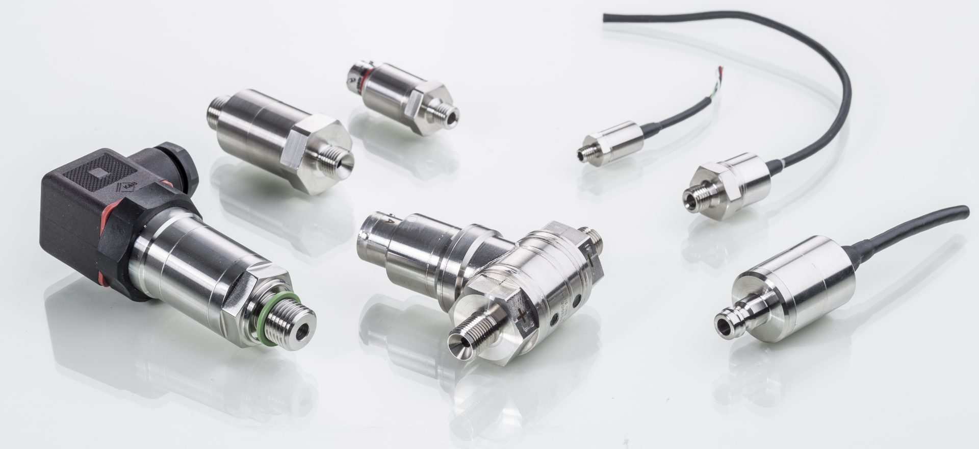
Discover our solutions when it comes to pressure measurement.
Select one of our pressure sensors with different sizes, temperature ranges and output signals.
Can’t find the ideal solution for you? Your Mission Impossible is our passion. Get in touch with us today. Our interdisciplinary team is looking forward to your inquiries.
Individual measurement task in pressure measurement
For devices that measure pressure, terms such as pressure sensor, pressure transducer, pressure transmitter, or even pressure capsule are used. All essentially describe the same characteristic. Pressure measuring devices capture the physical pressure of a medium and convert it into an electrical signal as a measure of that pressure.
Each type of pressure sensor is tailored to the particular requirements of specific measurement tasks. It is crucial to define what exactly the objective of the respective pressure measurement should be.
For example, measuring the hydraulic pressure on a working machine differs considerably from measuring the pressure on a gas meter. While in hydraulics the so-called alternating and overload resistance are in the foreground, the measurement at a gas meter requires a high accuracy. Every measurement error has a direct, positive or negative effect on the gas quantity counted. Both the gas supplier and the consumer have an interest in determining the gas quantity as accurately as possible, since it is the basis for calculating costs.
In the following, pressure sensors of different measuring principles for measuring liquids and gases are described. The focus is on the better known types available on the market. Supplementary information is given which can serve as guides for the practical selection of an optimum pressure sensor for an individual measurement task. Advantages and disadvantages are summarized in each case.
In addition to the technical characteristics, the expected operating costs should also make a decisive contribution to the purchase decision. The determination of anticipated operating costs is not easy, as it is made up of a large number of individual costs. First and foremost is always the purchase price.
Added to this are imputed costs, e.g. for
- a possible loss of use in the event of a device defect
- performance losses caused by measurement uncertainties
- Installation and cabling costs
- space requirements
- weight
- required display devices or interfaces
The optimum pressure sensor is the one that satisfactorily fulfills the requirements of a measurement task at an acceptable total cost.
Pressure types and typical application examples
In order to be able to select a pressure sensor, it is first important to know what type of pressure is to be measured. The pressure type indicates which reference point the pressure has, i.e. to which zero point of the pressure scale the pressure indication refers.
Pressure sensors are equipped with different measuring methods to match the desired pressure type.
Relative pressure sensors
About 90% of all pressure measurements are relative pressures. Relative pressure sensors measure the pressure of a medium relative to the atmospheric air pressure prevailing there. It is therefore also said that the pressure is measured relative to the atmospheric pressure. As a result, one obtains values that are either:
equal to the air pressure, i.e. neither higher nor lower than the air pressure; for example, the air pressure in a flat car tire. We use a relative pressure sensor to measure 0 bar relative pressure.
or greater than the air pressure; for example, the pressure in a car tire that is ready to drive. With the same relative pressure sensor, we measure e.g. 2.5 bar relative pressure there. This pressure is higher than the air pressure, i.e. it is greater than the latter. Colloquially, this pressure is therefore often referred to as 2.5 bar gauge pressure.
or smaller than the air pressure; for example, the suction pressure of a vacuum cleaner. Measured with the same relative pressure sensor, we get as a result e.g. – 30 mbar relative pressure. The minus sign indicates that the pressure is lower than the prevailing air pressure. Colloquially, this pressure is therefore referred to as 30 mbar negative pressure.
Differential pressure sensors
They have two pressure ports and measure the pressure difference between the two measuring chambers, in which different pressures may prevail. Pressure changes that affect both measuring chambers equally are not recorded. A differential pressure sensor is used for filter monitoring, for example. Here, the pressure upstream and downstream of the filter is measured. The dirtier the filter element, the greater the pressure drop. The differential pressure, which increases over the service life, is monitored in order to carry out filter cleaning if necessary.
Absolute pressure sensors
They measure the pressure of a medium relative to a vacuum integrated in the absolute pressure sensor. An absolute pressure sensor that is not exposed to any medium, which lies on the table, for example, measures the atmospheric pressure prevailing there, e.g. 1,000 mbar absolute pressure. Absolute pressure sensors that are designed exclusively for measuring atmospheric air pressure are called barometric pressure sensors. A particularly illustrative application is vacuum packaging technology. Here, the product to be packaged is placed in a foil bag. The air is then sucked out of the bag. The bag is evacuated to about 1 mbar absolute pressure and sealed. An absolute pressure sensor controls the process and triggers the sealing operation when all air has been removed except for a residual pressure of 1 mbar.
Measuring principles
Pressure is a mechanical variable. To be able to process it in automation technology, it must be converted into an electrical signal. Various physical effects resulting from the deformability of different materials due to the applied pressure are used for this purpose. A distinction is made between the following principles:
Piezoresistive pressure sensors
The pressure-sensitive element (membrane) consists of a silicon chip a few millimeters in size. Resistors are placed in this element by introducing foreign atoms.
The membrane is deformed by the applied pressure and the resistors are compressed (R2+R4) or stretched (R1+R3) (Fig. 2).
Compression and stretching result in reversible changes in the crystal structure and consequent changes in the resistances, which are proportional to the applied pressure. The four resistors are connected as a so-called Wheatstone bridge.
The resistance changes cause a change in the bridge voltage. In our example, we measure a bridge voltage of 0 mV in the unpressurized, unloaded state and 100 mV in the loaded state.
The silicon chip with the resistance bridge is sensitive to external influences. Only non-conductive, inert media can be measured with it. To make the piezoresistive measuring method universally applicable, the silicon chip with the bridge resistors is packaged in a so-called measuring cell. The measuring cell consists of a stainless steel body with a thin separating diaphragm.
All components are welded together without seals. The cavity between the silicon chip and the separating diaphragm is filled with a fluid to be able to transmit the process pressure. The measuring cell encapsulated in this way can be used universally, largely independent of the medium. It forms the heart of every piezoresistive pressure sensor.
Together with amplifier electronics, a pressure connection and an electrical connection, it becomes a finished device. The finished device is generally referred to as a pressure transmitter. Common outputs are voltage signals 0-5 volts, 0-10 volts, a current signal 4-20 mA or various digital interfaces such as CAN.
Due to their design, piezoresistive pressure sensors are mainly used for measuring ranges from 100 mbar to 150 bar. The measuring cell is variable and can be manufactured in all pressure types, absolute, relative and differential pressure.
| Advantages of piezoresistive pressure sensors |
|---|
| small design |
| all pressure types possible |
| front-flush variants |
| high overload resistance |
| exclusively stainless steel |
| weldable |
| no seal required |
| Disadvantages piezoresistive pressure sensors |
|---|
| separating diaphragm and coupling medium required |
| therefore higher manufacturing costs than other measuring principles |
Metal Thin Film Pressure Sensors
For the base body of a metal thin-film pressure sensor, stainless steel is formed into a circular ring diaphragm by a machining process. An insulating layer is first applied to this diaphragm. Then the material for strain gauges (DMS) and conductive tracks is vapor-deposited. In a photolithographic process, the actual structures of the strain gages are etched into the material. The operating principle and signal conditioning correspond to those of piezoresistive pressure sensors. Metal thin-film pressure sensors are extremely robust against vibrations and shock loads. They are mainly used for high pressure ranges from 10 bar up to several 1000 bar. The overload resistance is comparatively low (150%) due to the elastic steel. The stainless steel base body can be welded directly to a process connection. As with the piezoresistive pressure sensor, an integrated amplifier electronics measures the bridge voltage and converts it into all commercially available output signals. Metal thin-film pressure sensors are mainly manufactured as relative pressure sensors. Metal thin-film pressure sensors for measuring absolute pressure are technically complex to manufacture.
| Advantages of metal thin film pressure sensors |
|---|
| high measuring ranges possible |
| weldable |
| no seal necessary |
| high bursting strength |
| very good vibration and shock resistance |
| Disadvantages metal thin film pressure sensors |
|---|
| only pressure type relative pressure |
| no measuring ranges < 10 bar |
| low output signal |
Ceramic thick film pressure sensors
The basic body of a ceramic thick-film sensor is formed by a ring of aluminum oxide, the face of which is a closed membrane. On the outside of the membrane strain gauges are applied as thick-film resistance paste and baked in at high temperatures.
The diaphragm thickness is variable and defines the measuring range of the pressure sensor. Ceramic thick-film sensors cover measuring ranges from 2 bar to 100 bar. The media resistance of the ceramic body is very good. When integrating the ceramic into a metallic pressure connection, a seal is required that must be matched to the process medium. A major advantage of the ceramic is its almost hysteresis-free elasticity. As with the piezoresistive pressure sensor, an integrated amplifier electronics measures the bridge voltage and converts it into all commercially available output signals. The finished sensor also impresses with its excellent price-performance ratio.
| Advantages ceramic thick film pressure sensors |
|---|
| very good chemical resistance |
| insensitive to abrasive media |
| low manufacturing costs |
| Disadvantages ceramic thick-film pressure sensors |
|---|
| only relative pressure |
| seal required |
Capacitive ceramic pressure sensors
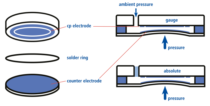
The measuring cell of a capacitive ceramic pressure sensor consists of a ceramic base body which, with a metallic surface, represents a capacitor plate (cp electrode). A thin, metal-coated counter electrode forms the pressure-sensitive membrane. A solder ring connects the cp electrode and the counter electrode and defines the plate spacing. When pressure is applied, the plate spacing changes and with it the capacitance between the electrodes. The membrane stroke is only about 30 µm. This change in capacitance is evaluated and then processed into an industry standard signal. This setup is suitable for pressures from 10 mbar to 25 bar. The overload protection is very high, since the diaphragm can move to a maximum of the counter-electrode and then rests there.
| Advantages Capacitive ceramic pressure sensors |
|---|
| very good chemical resistance |
| insensitive to abrasive media |
| high overload resistance |
| also suitable for low pressures |
| Disadvantages of capacitive ceramic pressure sensors |
|---|
| comparatively large design |
| Seal required |
Inductive pressure sensors
In the inductive pressure sensor, the change in magnetic flux is evaluated. It consists of a housing with two chambers. In the middle, between the chambers, there is a membrane to which a non-magnetic metal plate is attached. In the upper chamber housing there are two coils. The upper one is the reference coil, the lower one the measuring coil. While the reference coil is operated in isolation under constant magnetic conditions, the measuring coil changes its characteristic values depending on the distance of the metal plate. The movement of the metal plate due to pressure changes the magnetic flux of the measuring coil. The flux difference between reference and measuring coil is proportional to the diaphragm deflection and thus to the applied pressure. Designs equipped with 2 measuring chambers can measure relative pressures (positive or negative pressure) or differential pressures. Inductive pressure sensors are suitable for particularly low pressures in the measuring range down to 0.1 mbar (10 Pa). The areas of application are level measurement in small containers, overpressure monitoring in laboratories, hospitals or clean room
| Advantages of inductive pressure sensors |
|---|
| Suitable for measuring very low pressures |
| Disadvantages inductive pressure sensors |
|---|
| Low overload resistance |
| Large installation space |
| Sensitive to vibration |
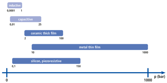
Typical measuring ranges of different measuring principles
Summary of the characteristics, advantages and disadvantages of pressure sensors of different measuring principles
Recommendation: In the table left column always integrate the word “pressure sensor” with = complete designation: name: Piezoresistive pressure sensors, Metal thin film pressure sensors, Ceramic thick film pressure sensors, Capacitive ceramic pressure sensors, Inductive pressure sensors.
| Advantages | Disadvantages | |
| Piezoresistive | Small design all pressure types possible front-flush variants high overload resistance exclusively stainless steel weldable no seal necessary | Separating diaphragm and coupling medium required |
| Metal thin film | high measuring ranges possible weldable no seal necessary high bursting strength very good vibration and shock resistance | Relative pressure only no measuring ranges < 10 bar low output signal |
| Ceramic thick film | very good chemical resistance insensitive to abrasive media low manufacturing costs | Relative pressure only Seal required |
| Capacitive | very good chemical resistance insensitive to abrasive media high overload resistance also suitable for low pressures | Comparatively large design Seal required |
| Inductive | Suitable for measuring very low pressures | – Low overload resistance – Large installation space – Sensitive to vibration |
DDM TIP: Mounting influences pressure sensors
After successfully selecting and purchasing a pressure sensor, it is easy to reduce its performance and measurement accuracy by improper mounting.
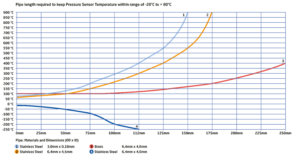
Temperature influences have the greatest impact on the measurement accuracy of a pressure sensor. A distinction must be made between the temperature of the medium being measured and the ambient temperature. While the medium temperature can be reduced by using a stub (see diagram), the ambient temperature has a direct effect on the pressure sensor with the electronics integrated in it.
When selecting a pressure sensor, its suitability must be checked accordingly. Depending on the measuring principle selected, vibrations or shocks can falsify the measuring result. Physically, small measuring ranges (<100 mbar) are particularly affected. Ideally, a vibration-free installation location should be chosen and the pressure connection should be made via a hose or pipe.
Depending on the measuring principle and measuring range, a position dependency may have to be taken into account. The nominal position selected by the manufacturer during calibration is specified in the data sheet. The most common nominal position is vertical, pressure connection at the bottom. If one deviates from this, a zero point error results. This error is usually so small that it is irrelevant for measuring ranges from 1 bar.
For measurements that require high accuracy, the manufacturer can be consulted. The smaller the pressure sensor, the more sensitive it is to excessive tightening torque when mounting the pressure connection. Most pressure sensors have specifications for the maximum tightening torque. If this tightening torque is exceeded, a measurement error, also known as a clamping error, is initially generated and the pressure sensor can be destroyed under certain circumstances.
When measuring pressure in liquids, fast-switching valves, gear pumps or other conditions can cause pressure peaks that are considerably higher than the actual system pressure. Such pressure spikes can damage a pressure sensor. If the likelihood of such spikes exists, work with the pressure sensor manufacturer to select the most appropriate measurement principle. Unexpected pressure spikes also occur in fluid lines that are not completely vented. It is generally advisable to mount a pressure sensor so that its pressure connection points vertically upwards. Any air or gases present will then vent themselves into the connected system.
Even if the mechanical arrangement and mounting are perfect, the measurement can be affected by electromagnetic interference coupled in via the measuring signal lines. Signal lines should be shielded and routed separately from high-energy lines.