
Turbine flow meters are dependent on the viscosity of the medium. In order to compensate for this effect, the fluid temperature is measured in the best case in contact with the medium. With the aid of a stored temperature to viscosity characteristic curve, the current media viscosity is calculated.
The wetted temperature measuring point in a measuring turbine is realized either by means of a Pt100/1000 resistance thermometer or via a thermocouple. These two temperature measurement methods are common in the industry and are used in many ways.
The following table compares the performance of these two temperature measurement methods in the application area of a turbine measurement system. Afterwards, the most important parameters accuracy, dynamics, installation space and cabling will be discussed in detail in the comparison. In addition, you will learn all about the added value of our in-house developed DDM turbine flow measurement system with thermocouple VCT.
| Measuring turbine with resistance thermometer Pt100 or Pt1000 | Measuring turbine with thermocouple |
|
Accuracy |
Accuracy |
|
Dynamics |
Dynamics |
|
Installation space |
Installation space |
 |
 |
Accuracy
Resistance thermometer Pt100 or Pt1000
Resistance thermometers are electrical components which exploit the temperature dependence of the electrical resistance of an electrical conductor to measure temperature. Platinum resistance thermometers Pt100/1000 are classified according to tolerance classes. These classes define a limit deviation within which the resistance thermometer must lie.
Class AA
Limit deviation: ± (0.1 + 0.0017 | t |) °C
Class A
Limit deviation: ± (0.15 + 0.002 | t |) °C
Class B
Limiting deviation: ± (0.3 + 0.005 | t |) °C
Class C
Limiting deviation: ± (0.6 + 0.01 | t |) °C
Usually, tolerance class A is used for turbine flow meters. Which results in a permissible deviation of ± 0.33°C (± 0.15 + 0.002 * 90°C) at a media temperature of 90°C.
Thermocouple
Thermocouples are based on the thermoelectric effect. If two wires of different materials are connected, a voltage can be measured at their free ends if the junction is at a different temperature level than these free ends.
The thermocouple types are named according to the material pairing. The type of thermocouple also describes the temperature range that can be used. The permissible limit deviations of a thermocouple are described in classes.
| Type | Measuring range | Class | Class 2 |
| T (Cu-CuNi) | -40 to 350°C | ±0,5°C | ±1,0°C |
| K (NiCr-Ni) | -40 to 1000°C | ±1,5°C | ±2,5°C |
| J (Fe-CuNi) | -40 to 750 °C | ±1,5°C | ±2,5°C |
| E (NiCr-CuNi) | -40 to 800°C | ±1,5°C | ±2,5°C |
Signal conversion
It is important to note that the tolerance classes only describe the accuracy of the temperature sensor used. Deviations due to signal transmission and analog-digital-analog conversion are not considered and must be added.
Some flow measurement systems provide the measured media temperature as an analog output signal. For this purpose, the previously analog-to-digital converted temperature value must be converted back to digital-to-analog.
In addition to the tolerance deviation of the temperature sensor, the analog output of the media temperature is loaded with the deviations of the AD converters and DA converters used. It is therefore not sufficient to assume the deviation of the temperature sensor as accuracy for the entire measuring chain.
DDM added Value
The thermocouple type T used by DDM has a calibrated deviation of max. ±0.25°C in the range of -20 to 100°C. Since this value also describes only the thermocouple, we calibrate each multiviscosity turbine for you at the three points -20°C, 30°C and 80°C. The thermocouple voltage is measured and digitized in the head of the DDM measuring turbine VCT. Thus, the temperature calibration certificate of the turbine VCT provides you with a statement on the measurement deviation of the thermocouple including A/D conversion. The achievable deviation is ±1.0°C, on request also ±0.5°C.
DDM measuring turbines VCT are operated with flow computers VCA. The calibrated digital temperature signal of the measuring turbine is converted to digital-analog in the flow computer and provided as analog output. The measurement deviation of the A/D conversion is documented in a calibration certificate.
Both calibration certificates, measuring turbine VCT and flow computer VCA, comprehensively describe the accuracy of the entire temperature measuring chain.
Dynamics
In turbine measuring systems, temperature measuring points are installed with a metallic sheath tube, which protects the temperature measuring point from the medium. Pt100/1000 resistance thermometers or thermocouples are embedded in a temperature-conductive encapsulation in the sheath.
The thin-film resistor of a Pt100/1000 is applied to a ceramic carrier, provided with connecting leads and embedded in a sheath tube.
In the case of thermocouples, the pair of materials is welded together, with the weld forming the measuring point. This measuring tip is also housed in a sheath tube.
In the case of rapid temperature changes, the sheath tube and potting must first be tempered for both measuring principles. In the case of the Pt100/1000 resistance thermometer, the mass of the ceramic carrier must also be tempered in order to record the medium temperature change.
In the case of a thermocouple, for systemic reasons, no further thermally inert mass is installed. The sheathed thermocouple therefore has a more dynamic response behavior.
Installation space
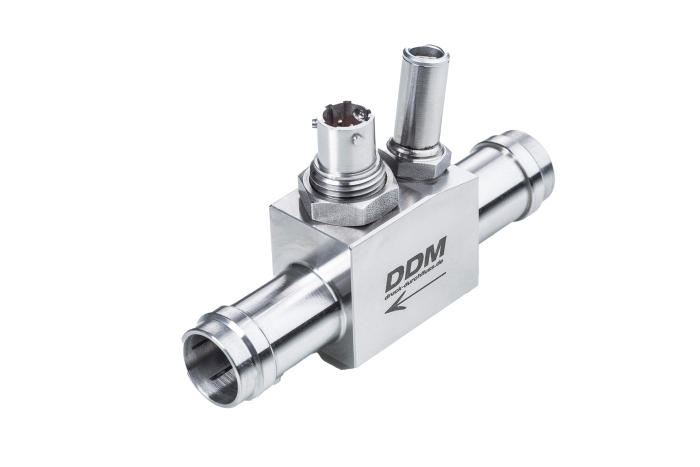
In turbine flow meters, a resistance thermometer is screwed in as an additional, separate component. This design is significantly larger than a measuring turbine with a temperature measuring point in the pickoff.
DDM added value
For DDM, one of the most important tasks in the development of the VCT measuring turbines was to minimize the installation space. Therefore, the wetted thermocouple type T was integrated directly into the turbine. In addition to the turbine frequency, the thermocouple voltage is measured and digitized in the turbine head.
Wiring
The variant with separately screwed-in Pt100 or Pt1000 resistance thermometer requires a second, additional measuring cable from the test turbine to the flow computer.
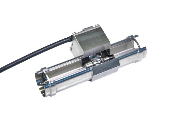
DDM added value
The sheath thermocouple is integrated directly in the housing of the DDM measuring turbine VCT. The thermocouple voltage is measured and digitized directly in the turbine head. The impeller speed, as a measure of the flow rate, is sampled without contact and also digitized in the turbine head. Both measured values, media temperature and impeller speed, are transmitted interference-free, digitally via a common measuring line to the flow computer for linearization and viscosity correction.